Share
It can be a surprise to learn that the quality of a GNSS receiver’s performance is largely limited by its antenna. Ken MacLeod looks at the factors you need to consider when picking an antenna

The antenna is the front end of the GNSS signal processing chain. To avoid signal degradation, the antenna must filter out interference from multipath and near- frequency signals to capture a clean and pure right hand circular polarised (RHCP) signal. A common analogy is comparing the GNSS antenna to the lens of a high- end digital camera. If the lens does not capture enough light or has distortions, the image captured and subsequent processing will be sub-optimal.
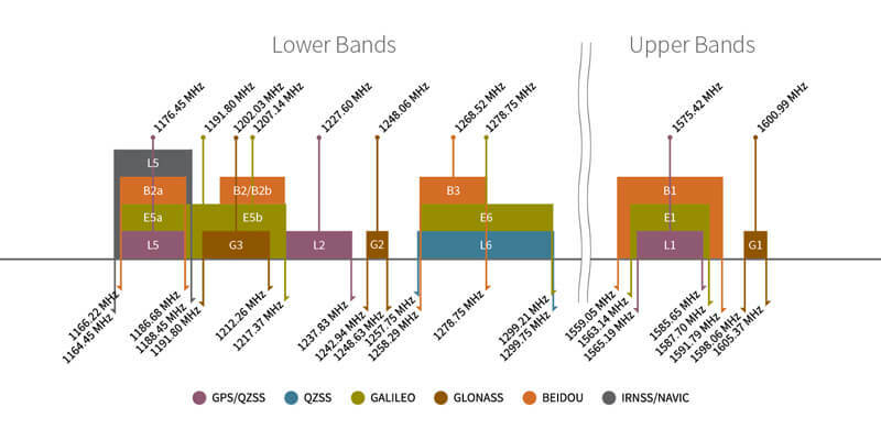
Unlike a few years ago, inexpensive high- precision multi-band GNSS receivers are now available. As a result, antenna designs have had to keep pace and now provide wideband coverage. The current GNSS frequencies and signals are grouped into two bands. The upper band, spanning from 1559-1606 MHz, was the first GNSS band available and included GPS-L1, GLONASS-G1, Galileo-E1 and BeiDou-B1 signals. New bands from all constellations are received in the lower- frequency band (1164-1300 MHz). If the antenna supports L-band correction services, the upper band ranges from 1539-1606 MHz (67 MHz bandwidth). The key features and characterisation parameters of full-band GNSS will be described in this article.
GNSS broadcast signals
GNSS signals are broadcast from medium Earth-orbiting (MEO) satellites. For example, GPS satellites are 20,200km above the surface of the Earth, but have low transmit power levels ranging from only 50W to 240W. As a result of the low transmit power and the distance travelled, the GNSS signals received on the Earth are very weak (as weak as -155dBW). As such, the receiving antenna must be able to capture and amplify received signals from the horizon to the zenith and from all azimuths.
Antenna designs
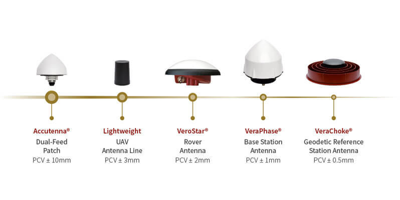
GNSS antennas have evolved over the years. Currently, many models meet the accuracy and precision required for most applications. Tallysman has designed and currently manufactures the following patented models: Accutenna, which uses a ceramic patch, Helical, VeroStar and, lastly, the cross-dipole based VeraPhase and VeraChoke antennas.
A ceramic patch Accutenna antenna is a general-purpose PNT antenna. It has a low profile and is approximately 70mm in diameter with a tight phase centre variation (PCV) (<10mm). A 10cm ground plane is required to achieve the best performance.
Helical antennas, on the other hand, do not require a ground plane and are small and light (~8g embedded and ~42g housed). They are ideal for handheld and UAV applications, as they are light and have a radiation pattern suitable for dynamic applications. The PCV is typically less than 5mm.
The VeroStar antenna’s key features are excellent element gain and radiation pattern. Both of which lead to excellent low-elevation angle tracking, resulting in an excellent antenna for land-survey or machine-control applications. PCV is in the ±2 mm range.
Lastly, the VeraPhase and VeraChoke antennas are ideal for reference stations, as they have very precise phase centre characteristics. The VeraPhase antenna’s PCV is ±1mm, while the VeraChoke antenna is approximately ±0.5mm.
Antenna gain
A GNSS antenna has two types of gain. The first type is the radiating gain from the antenna element and the second is provided by the low-noise amplifier (LNA). Antenna element gain at zenith typically ranges from a high of 8dBic for the VeraChoke antenna to ~2.5dBic for a small, lightweight helical or Accutenna antenna.
Low-noise amplifier features
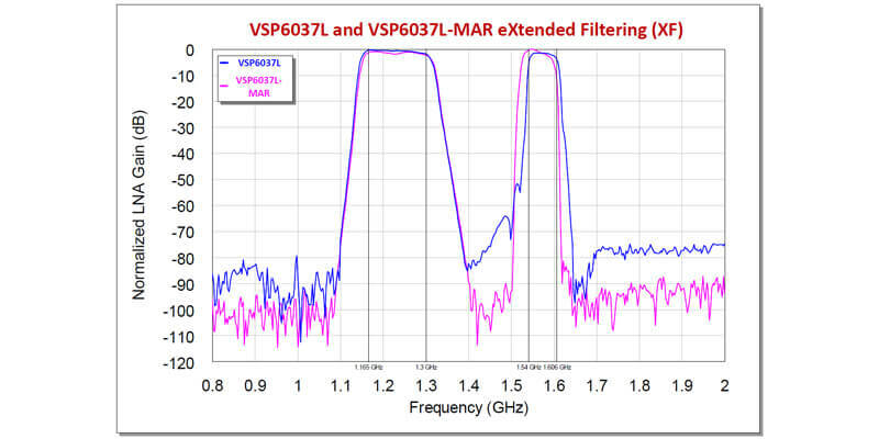
Low-noise amplifiers (LNA) are designed to provide two key functions: filter out-of-band signals and amplify in-band received signals. Every year, the radio frequency spectrum gets more congested. For example, a cellular signal broadcast at 800MHz can double to 1,600MHz, and this frequency lands in the middle of the GLONASS-G1 band.
To prevent out-of-band signals from entering and saturating the LNA, Tallysman uses a front-end filter and a comprehensive filtering strategy. The front-end filter enables the antenna to strongly attenuate out-of- band signals and prevent the antenna LNA from saturating. However, at the same time, a front-end filter will slightly increase the antenna’s noise figure, and that will cause the signal received by the GNSS receiver to have a slightly lower signal-to-noise ratio (SNR) than the same antenna design without a front-end filter. Thus, a good filtering system is essential to improve GNSS signal quality and ensure the antenna and GNSS system function in today’s crowded and noisy radio frequency environment.
Since the received signal power is very low, both a high-quality antenna element and LNA are required. It is important to note that antenna users should determine the recommended signal strength required by the GNSS receiver and the signal loss in the antenna cable. With this information, the required LNA gain can be selected. More gain than is required is not beneficial, as more amplification will affect both the GNSS signal and the noise in the environment. Typically, if the antenna cable run is short and the cable loss is low, an antenna gain of ~28dB is sufficient. Longer cable runs can require 35-50dB LNA amplification. In the case of a very long antenna cable run, an inline signal amplifier can be used.
Axial ratio
Another important characteristic is the antenna’s axial ratio. All GNSS signals are broadcast as RHCP signals. Ideally, the transmitted signal will describe a perfect circle. Problems happen in multipath environments such as urban canyons where delayed signal reflected on surfaces such as building or other structures. In these situations, the circular purity of the GNSS signals will be affected and the signals will start to describe an ellipse instead of a circle. Delayed signals due to multipath will add noise and phase shifts in the GNSS system. Therefore, they have to be attenuated by the antenna. The axial ratio reflects the ability of the GNSS antenna to attenuate multipath noise. A perfect antenna will have an axial ratio of 0dB (perfect circle) over all azimuths, elevation angles, and frequencies. An antenna with a good RHCP axial ratio will be able to capture more pure signals and mitigate multipath (typically elliptical or LHCP signals).
Antenna phase centre
To measure precise code and phase measurements, a GNSS antenna must concentrate the received radio frequency signals at a point. This point exists at both the GNSS satellite and at the user’s antenna. A helpful analogy is to think of a standard measuring tape where the zero end is the satellite broadcast phase centre, and the measurement end is the user’s antenna. Tallysman’s precision antennas have a stable well-defined phase centre and a small phase center variation (measured by a calibration facility) that enable the GNSS system to support precise and accurate real-time kinematic and precise point positioning applications.
Conclusion
In this brief article, I presented an overview of the key design objectives, properties, and characteristics of a GNSS antenna. The goal is to emphasise that scoring only the antenna noise figure and the gain is insufficient. Keep in mind that comprehensive filtering is required, and filtering will minimise the effects of near-band noise and harmonic signals. Users often compare one antenna to another by evaluating the GNSS receiver’s SNR values. When this comparison is made, keep in mind that a front-end filter will slightly increase the noise figure and decrease the signal-to-noise ratio of the received GNSS signals, but this will protect the antenna from saturation and improve system robustness. The axial ratio of an antenna characterises the purity of the RHCP signal and is a good indicator of multipath mitigation. Reviewing and field-testing the antenna parameters discussed will enable a non-radio frequency engineer to evaluate and select an ideal antenna for their application.
Ken MacLeod is product line manager, antenna products at Tallysman (www.tallysman.com)