Share
While geodesy is the science of accurately measuring and understanding the Earth's geometric shape, a variety of tools have been evolved to aid the task. Here, Fred Killet explains their characteristics and differences
In order to accurately measure the surface of the earth in any particular area, surveyors have, over time, created a complex network of measuring points. Firmly embedded in the ground, these are called reference points or benchmark monuments. By measuring the angles and distances between them, the latitude and longitude are determined for each.
Combining reference points into a group forms the basic data set for what is termed a Reference Frame. One or more Coordinate Reference Systems calculated from this Reference Frame are the basis for all geodetic tasks and for all types of surveying, mapping and navigation in a surveyed area. However, the way in which the coordinates are represented within each Coordinate Reference System (CRS) can vary.
Components of the CRS
For professional purposes, coordinate values alone are insufficient to prevent the incorrect positioning of objects.
For this reason, ISO 19111 standardises the process by specifying which descriptive information must be transferred when coordinates are exchanged and refers to this as the Coordinate Reference System (CRS).
Coordinate Reference System = Geodetic Reference System + Coordinate System
The components of the Coordinate Reference System and the requirements for the data transfer of coordinates are illustrated schematically in the following diagram.
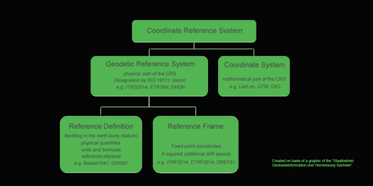
The Geodetic Reference System - in the parlance of the ISO 19111 called a Geodetic Datum - is the physical component of the Coordinate Reference System (e.g. ETRS89, DHDN, RD/83, 42/83).
The Coordinate System is the mathematical component of the Coordinate Reference System. It is defined by mathematical formulas that assign equivalent coordinates as numerical values to point positions (e.g. GK3, GK6, UTM, Lat/Lon, X/Y/Z). Coordinates are only unambiguous if the Coordinate Reference System is completely specified.
Effect of deviations in the CRS
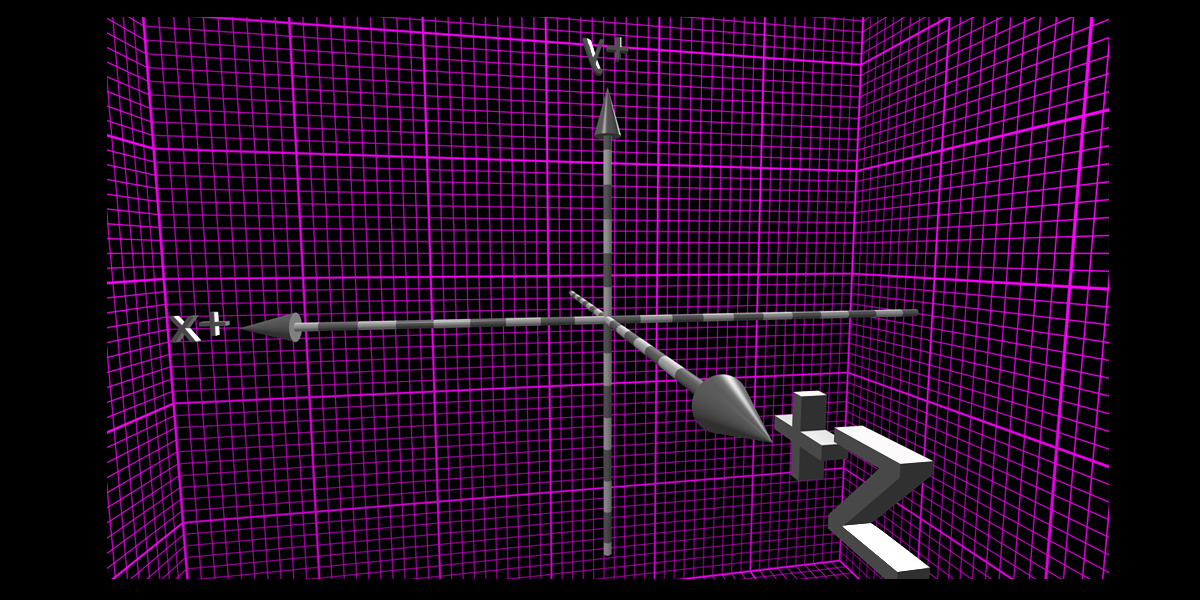
The use of different parameters of the Coordinate System, the geodetic Reference System, the Reference Definition or the Reference Frame will lead to more or less different results when transforming coordinates.
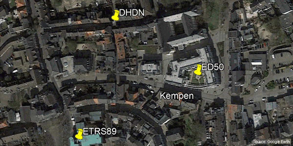
In the following image, as an example, the same geographic coordinate is shown in each of the different Reference Systems ETRS89, DHDN and ED50. As can be seen, the points are a several hundred meters apart.
Improving over time
In many countries, improved and thus more accurate variants of the same reference system have been made available over time. The different variants are usually identified by year numbers or accuracy and area information. When using different variants of the reference system, the location difference is usually small and is within the range of millimetres to meters. To correctly convert coordinates to another CRS, the same reference system must be used that was current when the coordinates were originally recorded.
The Helmert Seven Parameter Set is commonly used to define the reference system. In recent years, NTv2 grid files have been increasingly used to convert between reference systems. These offer very high accuracies, particularly in small-scale target areas, such as in Germany’s Federal States.
Accuracy, or rather inaccuracy, of the reference system is the result of minor deviations in the determination of points in the surveying process. For example, the DHDN was determined in the 19th century by measuring of triangular grids with optical theodolites. This measurement method, which is inaccurate according to today's understanding, led to relatively large distortions in the geodetic network. The reference system is the mathematical basis on which to calculate out these distortions and to create a homogeneous network on the underlying earth ellipsoid.
As examples, several variants of the reference system DHDN, which is commonly used in Germany, with different accuracies are shown here. Among others, the variants listed here are used in the program TRANSDATpro and in the Geodetic Development Kit GeoDLL (both see below) with the following designations:
DHDN/PD (DE 1995 ±5m), Rauenberg, Bessel
DHDN/PD (DE 2001 ±3m), Rauenberg, Bessel
DHDN/PD (DE Old states South ±1m), Rauenberg, Bessel
DHDN/PD (DE Old states Center ±1m), Rauenberg, Bessel
DHDN/PD (DE Old states North ±1m), Rauenberg, Bessel
DHDN90 (DE 2007 ±3.0m), Rauenberg, Bessel
DHDN90 (DE NTv2 BeTA2007 ±0.5m), Rauenberg, Bessel
DHDN90 (DE-BW NTv2 BWTA2017 ±5cm), Rauenberg, Bessel
DHDN90 (DE-BY 2019 NTv2 BY_KanU_Bges ±2cm), Rauenberg, Bessel
Special feature of the WGS84 Reference System
A special feature is to be considered when converting coordinates of a fixed Reference System into WGS84 - a dynamic Reference System that refers to the gravity center of the earth and which is influenced by the continental drift of the different continental plates.
This process describes the slow movement, splitting, and unification of continents on the earth's globe. The timing of these movements is constantly documented in the form of ITRS epochs. In addition to the parameters already described, the Reference Frame of the continent, together with the ITRS epoch at the time of the measurement or coordinate transformation, is required for calculations from and into WGS84. WGS84 coordinates can be accurately transformed to a fixed Coordinate Reference System only if the ITRS epoch of the WGS84 coordinates is known.
As an example, the Reference System ETRS89 which is fixed for the Eurasian Plate is considered here in more detail. At the 1989.0 epoch, the ITRS and the ETRS were identical. At this time, ETRS89 has been defined for the Eurasian Continental Plate and has been identified with the suffix 89. ETRS89 is firmly tied to the Eurasian Plate via fundamental stations and moves with about 2.5 cm per year over the global system defined by WGS84. It follows that the coordinates from an accurate current GPS measurement in the WGS84 Reference System in Europe can deviate by up to 80 cm from the actual coordinates in ETRS89.
Correct designation of a CRS
Here are some examples of the correct designation of a Coordinate Reference System:
UTM coordinates on the ETRS89 datum
Gauss-Krueger coordinates with three degree meridian stripes on the DHDN90 datum
Gauss-Krueger coordinates with six degree meridian stripes on the S42 datum
Geographical coordinates in DMS notation on the WGS84 datum at epoch 2005.
Another possibility for the unique naming of Coordinate Reference Systems is the use of EPSG codes. EPSG is a system of globally unique key numbers for Coordinate Reference Systems and other geodetic data and was originally established by a working group of European oil and gas exploration companies (European Petroleum Survey Group Geodesy). Information on EPSG codes is publicly-accessible from an online database. Here are some examples of EPSG codes of Coordinate Reference Systems and their usage:
3857 WGS84 / Pseudo-Mercator
is used by Google Maps, OpenStreetMap and map providers on the web
4326 WGS84 / Geographical Coordinates
is the worldwide system for GPS
25832 ETRS89 / UTM zone 32N
is used from 6°E to 12°E in Germany, Austria and Switzerland
25833 ETRS89 / UTM zone 33N
is used from 12°E to 18°E in Germany and Austria
31466 DHDN / Gauss-Krueger zone 2
is used west of 7,5°E in Germany
31467 DHDN / Gauss-Krueger zone 3
is used from 7,5°E to 10,5°E in Germany
Geodetic transformation software
The geodetic program TRANSDATpro (pictured below left) can convert coordinates between many Coordinate Reference Systems. The same applies to the Geodetic Development Kit GeoDLL (pictured below right), which allows the embedding of geodetic functions, e.g. coordinate transformations, into a user’s own software.
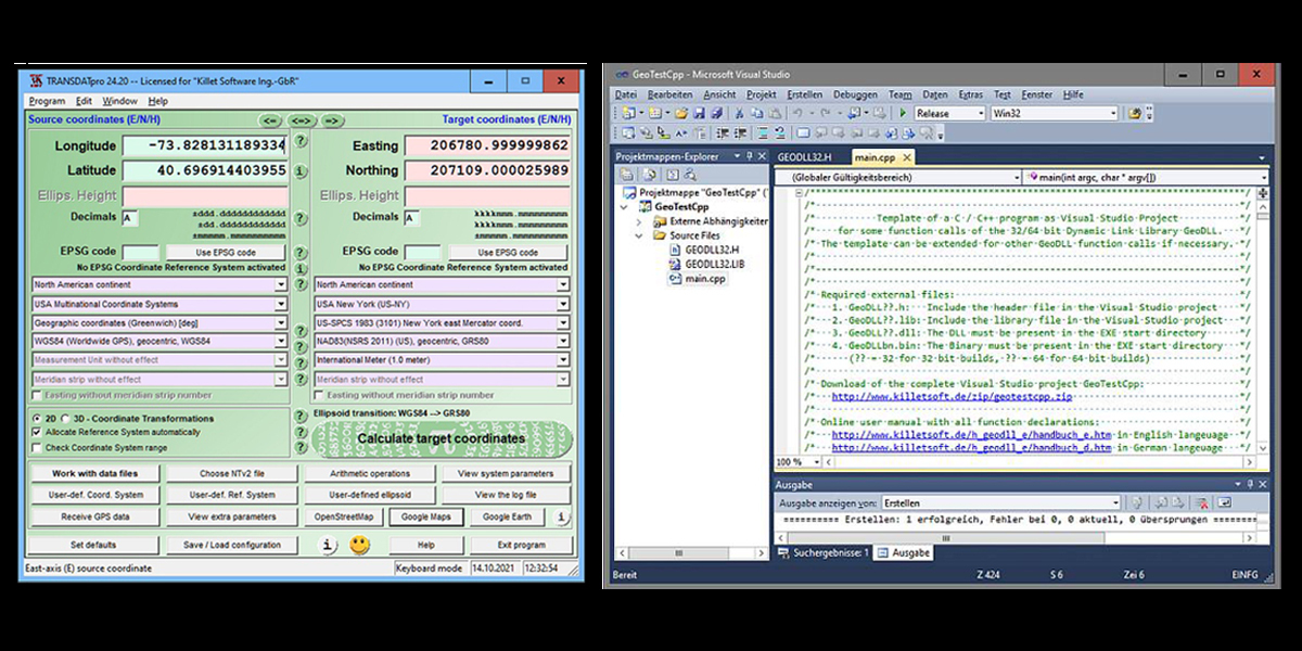
For coordinate transformations with the WGS84 Reference System, continental drift is considered in both tools by applying ITRS epochs. Detailed information about the software and the downloadable trial versions can be found on the KilletSoft website. The installation of the software is very easy, requiring just a few clicks.
Dipl.-Ing. Fred Killet is the managing director of Killet GeoSoftware in Kempen, Germany, a provider of geosoftware, geodata and geodetic development tools for geographers and GIS experts for high-precision coordinate transformations and geodetic tasks
Subscribe to our newsletter
Stay updated on the latest technology, innovation product arrivals and exciting offers to your inbox.
Newsletter